What Is the Purpose of a Sine Bar?
A sine bar with slip gauge blocks is used for precise angular measurement and used to measure sine bars very accurately or to detect any work that offered a high level of accuracy in measuring angles for milling, grinding, and inspection applications.
The sine bar is an exact angle measuring instrument. It is used to measures angles very accurately or to align the workpiece at a given angle. The sine bar is the most accurate tool for measuring angles.
The sine bar is made of high carbon, high chromium corrosion resistance steel. A sign bar is made with this material to avoid wear and tear of the sign bar when it is handled. As soon as tears and wear are avoided, errors are eliminated, and the accuracy of the sign bar is maintained.
Working Principle of Sine Bar:
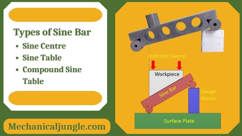
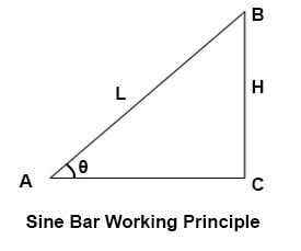
- The principle of operations of the sine bar is based on the law of trigonometry. If one roller of the sine bar is placed on the surface plate and the other roller is placed at the height of the slip gauge, the structure formed by the sine bar, surface plate, and slip gauge forms a triangle.
- The hypotenuse of these triangles is the sine bar, formed by combining vertical slug gauges and the surface plate base.
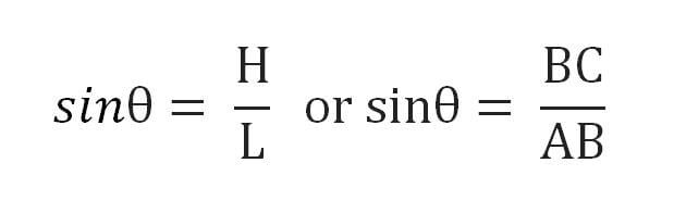
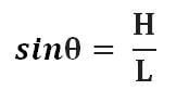
- Suppose the height of the slip gauge is H and the length of the sine bar is L, then the sine ratio will be H divided by the angle L theta.
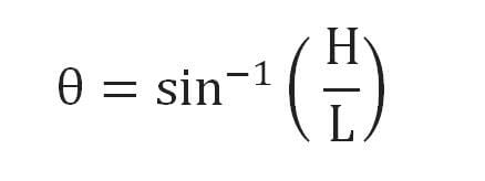
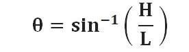
- Now the angle θ can be calculated as the sin inverse of H divided by L.
Construction of Sine Bar:
- The sine bar has a gauge body made of a rigid material such as steel. There are two rollers at the end of the steel bar. The rollers are of equal diameter, and the axes of these rollers are parallels to each other.
- The top of the steel bar parallels the line through the centers of the two rollers.
- The length of the sine bar equals the distance between the center of the two rollers.
- The length of the sine bar is either 100 mm, 200 mm, or 300 mm. This length is very precise and precise.
- Relief holes are provided to reduce the weight of the bus sine bar.
Only a sine bar cannot be used for the measurement of angles of a component alone. The sine bar is always used for the measurement of angles with slip gauges and elevation gauges.
Surface Plate:
- A surface plate is used as a base for arranging the sine bar and other components such as slip gauges and height gauges.
- It can be assumed that the surface plates provide the precise horizontal surface to the sine bar.
- If we have a sine bar on the surface plate, the top surface of the sine bar should be parallel to the horizontal surfaces of the surface plate.
Dial Gauge:
- A dial gauge is used to check surface uniformity. If a dial gauge shows zero deflections while travelings on the surface, we can say that the surface is parallel to its base.
- In the sine bar arrangement, dial gauges are used to measure whether the upper surface of the workpiece is parallels the surface plate or to measure the angle of the tapered sine of the workpiece.
Block Gauges or Slip Gauges:
Block gauges or slip gauges are standards for measurings the height or lengths of objects in a very precise manner.
Vernier Height Gauge:
A vernier height gauge is used to measures the height of the roller of the sine bar to measure the angle of a larger component.
Working of Sine Bar:
Sine bars are used in different ways to measure the angle of different types of workpieces.
- Working when the angle of a small component is to be measured.
- Working when the angle of a large component is to be measured.
#1. Working when the angle of a small component is to be measured-
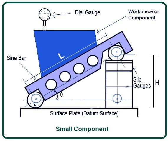
- Measure the angle of small components; the sine bar is set approximately at an angle to the surface plate by placing a roller of the sine bar on a combination of the appropriate gauge slip.
- The components whose angle is to be measured are placed above the sine bar. Dial gauges are used to check whether the upper surface of the component is parallel to the surface plate.
- This dial gauge is carried over the component throughout its length.
- The variation in the parallelism of the upper surface of the component and the surface plate can be detected by the deflection of the indicator of the dial gauge.
- After that, the height of the slip gauge is adjusted by adding or removing the block of the slip gauge.
- This is adjusted until the reading of the dial gauge falls to zero over the entire length of the component.
- When this condition is met, the angle of the component becomes equal to the angle of the sine bar above the surface plate.
- Now the angle of the sine bar above the surface plate can be easily measured by the sine inverse of H divided by L, where H is the height of the slip gauge & L is the length of the sine bar.
where,
- θ = angle of the component to be measured.
- H = height of the slip gauges.
- L = length of the sine bar.
#2. Working when the angle of a large component is to be measured-
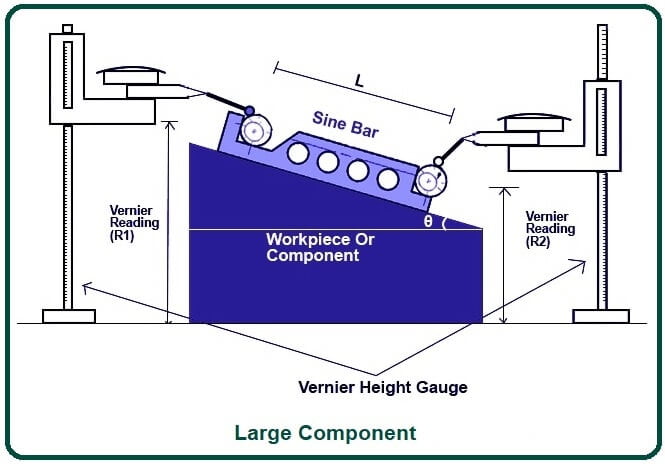
- In the case of a large component, the sine bar is placed above the component because the component cannot be placed above the sine bar.
- When the sine bar is placed on a larger component, the lower surface of the larger component is parallels the datum surfaces. The Sine bar is placed on the uppers surfaces of the component. The top surface of the component is bent, and its angle is to be measured.
- The sine bar on the upper surface is also in an inclined position, and there is a difference in the heights of the two rollers of the sine bar.
- The heights of the two rollers are measured using a Vernier height gauge, and the height of the two rollers is written as H1 and H2. Here the height of H1 is greater than H2.
- The difference in height H1 and H2 is the rise of the sine-bar.
- Measurings pressure is also measured using a dial gauge. The altitude gauge holds until the dial gauge readings become zero each time.
The angle of these large components is evaluated using the formula given below:
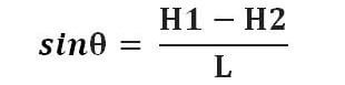
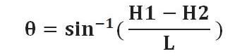
where,
- θ = angle of the component to be measured.
- H1 = height of the upper roller.
- H2 = height of a lower roller.
- L = length of the sine bar.
Conditions Required for Accurate Reading of Sine Bar:
- Axes of the two rollers of the sine bar must be parallels to each other.
- The upper surfaces of the sine bar should be parallel and perfectly flat.
- The rollers in the sign bar should be of the same diameter.
- The distance between the centers, i.e., L, should be measured accurately.
Types of Sine Bar:
Various sign bars are available according to the purpose of their use and method of application. Some types of sign bars are:
- Sine Centre.
- Sine Table.
- Compound Sine Table.
#1. Sine Centre-
- This type of OS sine bar is used to measure the angles of conical objects that have male and female parts.
- The sign center cannot measure angles greater than 45 degrees.
#2. Sine Table-
- The signing table is a special type of sign bar that is large and wide.
- This sine bar has a mechanism for locking it after positioning, which is used to hold the workpiece during operation.
#3. Compound Sine Table-
- A compound sign table is used to measure the angles of a large workpiece that cannot be measured using a simple sine bar.
- In compound sign tables, two sign tables are placed at right angles to each other.
- These tables can be rotated to obtain the required integration.
Limitations of Sine Bar:
Following are the limitations of sine bar:
- Any unknown estimate present in the component will cause errors to measure the induced angle.
- For the construction of slip gauges, there is no scientific approach available, and it has to be built on a trial & error basis, and it is a time-consuming process.
- During angle measurement using a sine bar, the sine bar length must be greater than or equal to the length of the component to be inspected.
- If the length of the inspected component is too long, there is no sine bar available that is longer than the component. In these cases, a sine bar with a height bar will be used for measurement.
Applications of Sine Bar:
Following are the applications of the sine bar:
- The sine bar is used to set or determine the workpiece at a given angle.
- To investigate the measurement of unknown angles in the workpiece.
- Some specially designed sign bars are used to mount the workpiece to perform conical-shaped machining for the workpiece.
- I am investigating unknown angles on heavy components.
- To check the taper key angles.
- To check the flatness of the surface.
FAQ: The Purpose and Applications of a Sine Bar in Precision Engineering
What is a sine bar?
A sine bar is an exact angle measuring instrument used for precise angular measurements in milling, grinding, and inspection applications. It is made of high carbon, high chromium corrosion-resistant steel to ensure durability and accuracy.
What is the primary purpose of a sine bar?
The primary purpose of a sine bar is to measure angles very accurately or to align a workpiece at a given angle. It is considered one of the most accurate tools for measuring angles.
How does a sine bar work?
A sine bar works on the principle of trigonometry. It forms a triangle with a surface plate and slip gauge blocks. By measuring the height of the slip gauge (H) and the length of the sine bar (L), the angle (θ) can be calculated using the sine inverse formula: θ = sin⁻¹(H/L).
What materials are sine bars made from?
Sine bars are made from high carbon, high chromium corrosion-resistant steel to prevent wear and tear, thereby maintaining accuracy.
What are the key components of a sine bar setup?
The key components of a sine bar setup include:
- The sine bar itself.
- A surface plate, which provides a precise horizontal base.
- Slip gauges or block gauges, which are used to measure height precisely.
- A dial gauge to check surface uniformity and ensure parallelism.
- A vernier height gauge for measuring the height of the sine bar’s rollers.
How is a sine bar used to measure the angle of a small component?
To measure the angle of a small component:
- Place one roller of the sine bar on a combination of slip gauges to set it at an approximate angle.
- Position the component on the sine bar and use a dial gauge to ensure the upper surface is parallel to the surface plate.
- Adjust the height of the slip gauges until the dial gauge shows zero deflection.
- Calculate the angle using the sine inverse formula.
How is a sine bar used to measure the angle of a large component?
For large components:
- Place the sine bar on top of the component.
- Measure the height difference between the two rollers using a vernier height gauge.
- Use the difference in heights (H1 and H2) to calculate the angle with the sine inverse formula.
What are the conditions required for accurate readings with a sine bar?
For accurate readings:
- The axes of the two rollers must be parallel.
- The upper surface of the sine bar should be flat and parallel.
- The rollers should have the same diameter.
- The distance between the centers of the rollers should be measured precisely.
What are the different types of sine bars?
The different types of sine bars include:
- Sine Centre: Used for measuring angles of conical objects.
- Sine Table: A large and wide sine bar with a locking mechanism for holding workpieces.
- Compound Sine Table: Consists of two sine tables placed at right angles to each other, used for measuring large workpieces.
What are the limitations of a sine bar?
Limitations include:
- Any unknown errors in the component can affect the measurement.
- The construction of slip gauges is time-consuming and based on trial and error.
- The sine bar length must be equal to or greater than the component length.
- For very long components, a sine bar with a height bar is used.
What are the applications of a sine bar?
Applications include:
- Setting or determining workpieces at a given angle.
- Investigating unknown angles in workpieces.
- Mounting workpieces for conical-shaped machining.
- Checking taper key angles and surface flatness.