Working of Draft Tube:
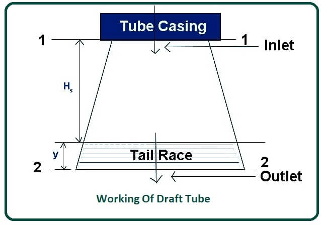
- In the case of turbines such as the Kaplan turbine and Francis turbine, the head available at the inlet is generally low, so the turbine is positioned much closer to the tailrace to achieve maximum head as most of the water pressure changes to the turbine’s mechanical energy, the pressure head at the outlets of the turbine is below atmospheric pressure.
- Since the exhaust of the turbine is placed near the run of the story and the water pressure at the exit of the turbine is less than the atmospheric pressure, it can cause water backflow.
- This is because, at the exit of the turbine, the water flows from high pressure to low pressure and pressure and is lower than atmospheric pressure.
- The backflow of water causes severe damage to the turbine and its various parts and may prevent the turbine from functioning.
- Avoids this problem of backflow; a draft tube is used between the outlet of the turbine and the tailrace. The draft tube raises the water pressure to atmospheric pressure.
Applying Bernoulli’s Principle at sections 1-1 and 2-2
[ Pressures Head + Velocity Head + Elevation Head]1-1 = [Pressure Head + Velocity Head + Elevation Head ]2-2
Let,
- P1 = pressure of the fluid at section 1-1 (an inlet of a draft tube).
- V1 = velocity of the fluid at section 1-1 (an inlet of a draft tube).
Similarly,
- P2 = pressure of the fluid at sections 2-2 (outlet of the draft tube).
- V2 = velocity of the fluid at sections 2-2 (outlet of the draft tube).
- ρ = densities of flowing fluid
- g = gravitational force
- hf = loss of head (energy) in the draft tube
- Hs = verticals height of draft tube above the tailrace
- y = distance of the bottom of the draft tube from the tailrace.
- Pa = atmospheric pressure of the fluids.
( P1 / ρg ) + ( V12 / 2g ) + ( Hs + y ) = ( P2 / ρg ) + ( V22 / 2g ) + ( 0 + hf )
( P1 / ρg ) = ( P2 / ρg ) – ( Hs + y ) + ( V22 / 2g ) – ( V12 / 2g ) + hf
Pressures head at sections 2 – 2 is equal to atmospheric pressures head and distances y.
( P2 / ρg ) = ( Pa / ρg ) + y
( P1 / ρg ) = ( Pa / ρg ) + y – Hs – y + ( V22 / 2g ) – ( V12 / 2g ) + hf( P1 / ρg ) = ( Pa / ρg ) – Hs + ( V22 / 2g ) – ( V12 / 2g ) + hf
Converting the equations for our requirement (i.e., in the middles of R.H.S taking “-” commons)
( P1 / ρg ) = ( Pa / ρg ) – Hs – [ ( V12 / 2g ) – ( V22 / 2g ) – hf ]
In the above equations [ ( V12 / 2g ) – ( V22 / 2g ) – hf ] is called kinetics head.
Here [ ( V12 / 2g ) – ( V22 / 2g ) ] is the dynamics head.
From the above equation, we can write.
( P1 / ρg ) < ( Pa / ρg )
So P1 < Pa
The pressure head at the inlets of the draft tube or outlet of the turbine is less than the atmospheric pressure. So the net head on the turbine with the draft tube increases.
Where Is the Draft Tube Used?
- The draft tube is a connecting pipe that is usually fitted at the outlet or exhaust of the turbine, which converts the kinetic energy of the water to static pressure at the outlet of the turbine.
- This helps to avoid the dissipation of the kinetic energy of the water flowing through the outlet of the turbines.
- It is usually fitted in power turbines such as reaction turbines, Kaplan turbines, or Francis turbines.
- The diameter of the draft tube is small near the inlet and large near its outlet. The outlet of the draft tubes is always submerged in water.
- The draft tube increases the pressures of the exit fluid in its kinetic energy and velocity. This increases the capacity of the turbines. It is located just below the runner and allows the flow velocity to exit from the runner.
- The materials used to make draft tubes are cast steel and cement concrete. The efficiency of a draft tube is the actual kinetic energy that is converted to static pressure.
The Efficiency of Draft Tube:
The efficiency of draft tube Ƞd = Actual conversion of kinetic energy to pressure heat at the inlet of the draft tube.
Therefore,
- Ƞd = (Actual conversions of kinetic energy into pressure head)/(Total Kinetic energy present at inlet of the draft tubes)
- Ƞd= [ ( V12 / 2g ) – ( V22 / 2g ) – hf ] / [ ( V12 / 2g ) – ( V22 / 2g ) ]
- Actuals conversion of kinetic head into pressures head = [ ( V12 / 2g ) – ( V22 / 2g ) – hf ]
- Theoretical conversion of kinetic head into pressures head = [ ( V12 / 2g ) – ( V22 / 2g ) ]
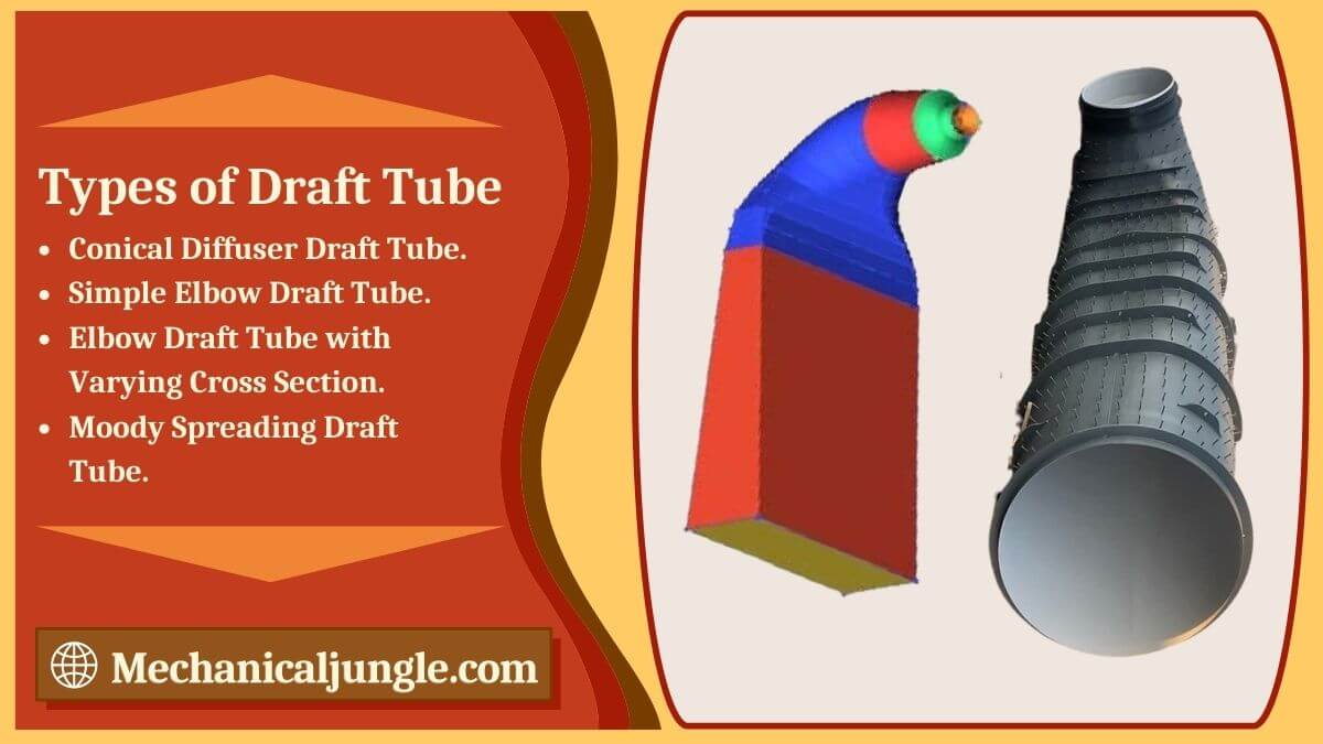
Types of Draft Tube:
Draft tubes are mainly classified into four types, and those are:
- Conical Diffuser Draft Tube.
- Simple Elbow Draft Tube.
- Elbow Draft Tube with Varying Cross Section.
- Moody Spreading Draft Tube.
#1. Conical Diffuser Draft Tube-
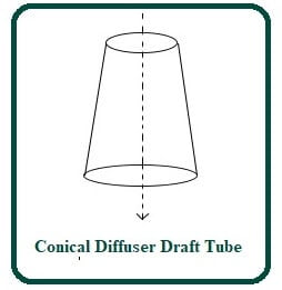
- In this type of draft tubes, the flow path is straight & divergent. This draft tube is made with mild steel plates.
- It is thin in size, and the diameter of the outlet is larger than the inlet diameter of this draft tube.
- The tapered angles of the draft tube should not be too large as it will cause separation of the flow from the draft tube wall.
- This angle should not be too small because it requires a long draft tube which causes a significant loss of kinetic energy. So the taper angle is always about 10 degrees.
#2. Simple Elbow Draft Tube-
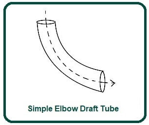
- In a simple elbow draft tube, the tube is elbow-shaped. It is mainly used in Kaplan turbines. In this type of draft tube, the cross-section area remains the same throughout the length of the draft tube.
- The inlet & outlet of the draft tube is circular. This draft tube is usually used at low head locations, and the turbine is to be placed close to the tailrace.
- This helps cut the cost of digging, and the exhaust diameter must be as large as possible to recover kinetic energy at the runner’s outlet.
#3. Elbow Draft Tube with Varying Cross Section-
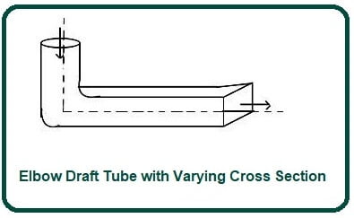
- The elbow draft tube with different cross-sections is an improvement of the simple elbow draft.
- In this type of draft tube, the inlets are circular, and the outlet is rectangular in shape.
- The horizontals portion of the draft tube is usually tilted upward to prevent air ingress from the exit end.
- The cross-section area of the type of draft tubes varies from inlet to outlet. The outlet of this draft tube is always below the tailrace.
- It is commonly used in Kaplan turbines, and the efficiency of this type of draft tube is about 70 percent.
#4. Moody Spreading Draft Tube-
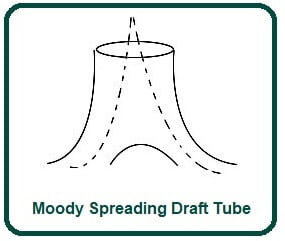
- In this type of draft tube, an outlet of the draft tube is divided into two parts. It is similar to a conical draft tube and is provided with a central core part that divides the outlet into two parts. This draft tube has one inlet and two outlets.
- This type of draft tubes is mainly used to reduce the swirling action of water.
- It is used in vertical shaft turbines. The efficiency of this type of draft tube is about 88 percent.
The Function of a Draft Tube:
This reduces the velocity of the fluid and therefore increases the pressure of the fluid to atmospheric levels.
Advantages of a Draft Tube:
- It is one of the important components that is used to convert water into energy.
- It is found in the piping system, dam, where it is difficult to deliver mechanical work to the turbine.
- The draft tube prevents the splendor water from coming out of the runner and carries its guide water to the teller.
Applications of a Draft Tube:
- It is used to increase the surrounding pressure by a lower turbine exhaust pressure, thereby rejecting the fluid.
- So this is the observation about the draft tube; I hope I will be able to distribute my knowledge well; feel free to ask your doubts in the comments section; otherwise, you ask us directly on our community portal can.
- And don’t forget to share this stuff with your circle of friends and help them learn more about the draft tube.
Frequently asked questions (FAQs) that you could include in your article about draft tubes in turbines:
What is a draft tube in turbine technology?
A draft tube is a crucial component in turbine systems that helps convert kinetic energy from flowing water into pressure energy, thereby increasing turbine efficiency.
Why are draft tubes necessary in turbines?
Draft tubes are necessary because they prevent water backflow, which can damage turbines. They also help maintain pressure and optimize energy conversion from kinetic to mechanical energy.
What are the main types of draft tubes used in turbines?
The main types include Conical Diffuser, Simple Elbow, Elbow with Varying Cross-Section, and Moody Spreading draft tubes, each designed for specific turbine configurations and efficiency goals.
How does a draft tube work to increase turbine efficiency?
By providing a controlled path for water exiting the turbine, draft tubes reduce kinetic energy loss and increase static pressure, maximizing the turbine’s power output.
Where are draft tubes typically used?
Draft tubes are commonly found in hydropower plants utilizing Kaplan and Francis turbines, where maintaining optimal pressure and velocity of water flow is critical for efficient energy production.
What materials are draft tubes made from?
Draft tubes are typically constructed from materials like cast steel and cement concrete, chosen for their durability and ability to withstand high-pressure water flows.
What factors affect the efficiency of a draft tube?
Efficiency can be influenced by factors such as the design of the draft tube (including taper angles and cross-sectional variations), flow dynamics, and the height of the draft tube above the tailrace.
What are the advantages of using draft tubes in turbine applications?
Draft tubes enable turbines to operate more efficiently by converting kinetic energy into pressure energy, thereby increasing overall power generation capacity and reducing operational costs.
Are there specific maintenance requirements for draft tubes?
Regular inspection and maintenance are necessary to ensure draft tubes remain free from debris buildup and structural integrity issues, which could impact turbine performance.
How does the efficiency of draft tubes impact hydropower generation?
Higher draft tube efficiency directly correlates with improved hydropower generation capabilities, making them a critical component in maximizing the output and reliability of hydropower plants.