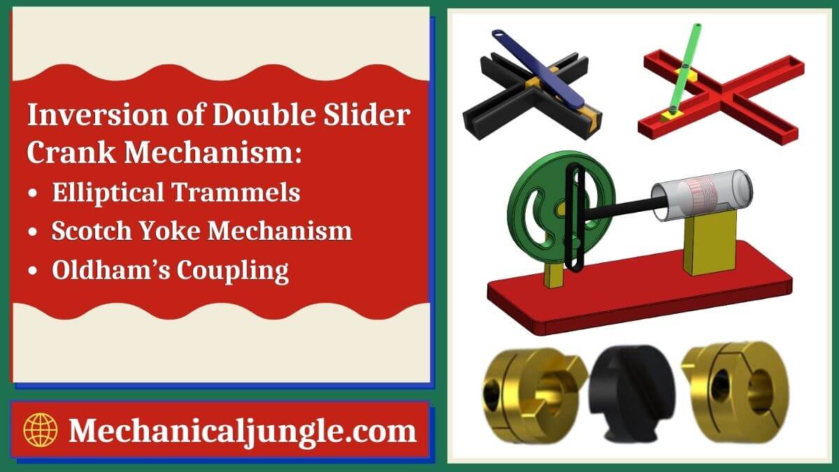
Inversion of Double Slider Crank Mechanism:
The double slider crankshaft has two sliding pairs and two twist pairs. It is named double slider crankshaft because it has two sliding pairs. It has two sliders, a frame in which the slider moves, and a link that connects the two slides and fixes the distance between the two sliders.
The frame in which sliders move is a combination of two straights grooves that form a single link and cut eaches other at right angles.
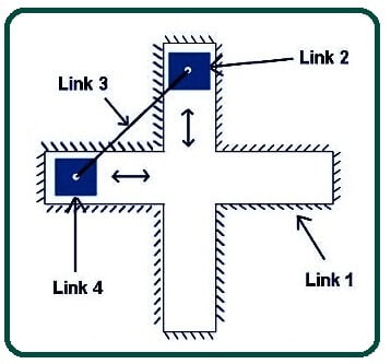
In a different inverse of double slider crank chain: –
- The frame is Link 1.
- The first slider is link 2.
- The bar connecting two sliders is Link 3.
- The second Slider is Link 4.
There are three important inversions of the double slider crank chain. These three are:-
- Elliptical Trammels.
- Scotch Yoke Mechanism.
- Oldham’s Coupling.
#1. Elliptical Trammels:-
- This type of inverse is used to draw the ellipse. It is also known as the trend of Archimedes. It can be used to draw ellipses of different sizes.
- In this inverse link 1, i.e., the frame is fixed. Both sliders, link 2 and link 4, run in the grooves of this frame. One slider moves vertically, and the other slider moves horizontally.
- The connecting rod link 3, which connects the two sliding bars, link 2 and link 4, constrain the motion of these sliding bars. While the two sliders move, each point in the connecting rod is the location of an ellipse.
- The different points in the connecting rod will draw a different ellipse.
#2. Scotch Yoke Mechanism:-
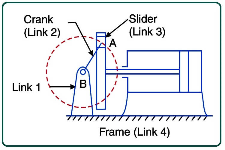
- Scotch Yoke mechanisms are used for converting rotary motion into a reciprocating motion. The inversion is obtained by fixing either link 1 or link 3. In, link 1 is fixed. In this mechanism, when link 2 (which corresponds to crank) rotates about B as center, link 4 (which corresponds to a frame) reciprocates. The fixed link 1 guides the frame.
- Now, the second slider will rotate around the fixed slider and will draw a circle if its path is traced. If the frame or slanted plate will move forward and if the horizontal moving slider is fixed and the frame will move up and down, then the vertical moving slider is fixed.
#3. Oldham’s Coupling:-
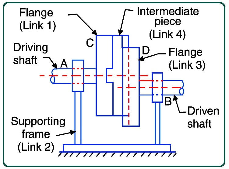
- Oldham couplings are used to connect two shafts whose axles are separated from each other and rotate them at equal speed.
- An Oldham coupling mechanism is used to connect two parallel shafts whose axes are separated at short distances. The shaft is coupled in such a way that if one shaft rotates, the other shaft also rotates at the same speed. This inverse is achieved by fixing link 2. The shaft to be connected have two flanges (link 1 and link 3), fastened strictly to their ends by forging.
- It forms the coupling of the inverted Oldham. Now we will discuss how it is used to connect two shafts whose axis is slightly different from each other.
- This shaft is connected in such a way that if one shaft rotates, the other shaft also rotates at the same speed.
- The two flanges are placed at the end of the two shafts that are to be connected. These flanges are rigidly fastened at the end by forging. Both flanges have grooves.
- The groove of both flanges is perpendicular to each other. Between these two flanges, a central flange is inserted, which fits into the grooves of both flanges.
- In this coupling, which is fixed frame links 3, driving shaft and driving flange for link 2, intermediate flange link 1, and driveshaft and flange form link 4.
- When the first shaft, i.e., The driving shaft, rotates, the forged one also rotates, and then the central flange placed in the grooves of the driving flange starts rotating.
- Then the driven flange also starts rotating because the center flange is also fixed in the grooves of the driven flange, and as the driven flange rotates, the driven shaft also starts rotating at the same speed.
FAQ
What is a double slider crank mechanism?
A double slider crank mechanism consists of two sliding pairs and two turning pairs. It features two sliders that move within a frame, connected by a link that maintains their relative distance.
What are the key components of a double slider crank mechanism?
The components include:
-
- Frame (Link 1): Provides the structure within which the sliders move.
- First Slider (Link 2): Moves vertically or horizontally within the frame.
- Connecting Bar (Link 3): Connects the two sliders and restricts their motion.
- Second Slider (Link 4): Moves in conjunction with the first slider.
What are the main inversions of the double slider crank mechanism?
The three main inversions are:
-
- Elliptical Trammels: Used for drawing ellipses of various sizes.
- Scotch Yoke Mechanism: Converts rotary motion into reciprocating motion.
- Oldham’s Coupling: Connects two shafts at a slight distance and ensures equal speed rotation.
How does Elliptical Trammels work?
In Elliptical Trammels, the frame (Link 1) is fixed, while both sliders (Link 2 and Link 4) move within its grooves. The connecting rod (Link 3) constrains their motion to trace out ellipses of different sizes.
What is the application of Scotch Yoke Mechanism?
Scotch Yoke Mechanism is used in applications where rotary motion needs to be converted into reciprocating motion, such as in engines and pumps.
How does Oldham’s Coupling connect two shafts?
Oldham’s Coupling connects two shafts that are slightly offset from each other. It uses three discs (flanges): one fixed (Link 2) and two driving (Link 1 and Link 3), which rotate together to transmit motion between the shafts.
What are the advantages of using double slider crank mechanisms?
Advantages include simplicity in design, precise control over motion, and versatility in converting between different types of motion (rotary to reciprocating and vice versa).
Where are double slider crank mechanisms commonly used?
They are found in various mechanical systems such as engines, machine tools, and devices requiring precise motion control and conversion.
How can one choose the right inversion of the mechanism for a specific application?
The choice depends on the required motion type (rotary or reciprocating), the degree of precision needed, and space constraints. Each inversion offers unique advantages suitable for different applications.
What are the limitations of double slider crank mechanisms?
Limitations include potential wear due to sliding components, complexity in adjusting for different motion characteristics, and the need for periodic maintenance to ensure smooth operation.